Calibration and display of well log images
- Former user (Deleted)
- Erlend Kvinnesland
Getting a well log image
The documentation describes how to calibrate and display a well log image taken from a well log report; for instance using NPD's facta pages to get NPD's facta reports for a specific well.
Save the image of the well logs on disk in an appropriate format (PNG, JPG, BMP etc.). If the report is in a PDF file and you cannot save the image, read in the PDF file with Ghostscript (f.inst) which is freeware and save the image.
Read the image into a Generic folder in Geocap using Import and Automatic reading. If the image is greyscale you should set the reader option to read greyscale images as images (not as grids) in the import dialog.
Before you import the images you may want to edit the image in an image editor of some kind. (Photoshop, Gimp, Microsoft Paint). This may be removing parts of the image you do not need.
On this page:
Calibration
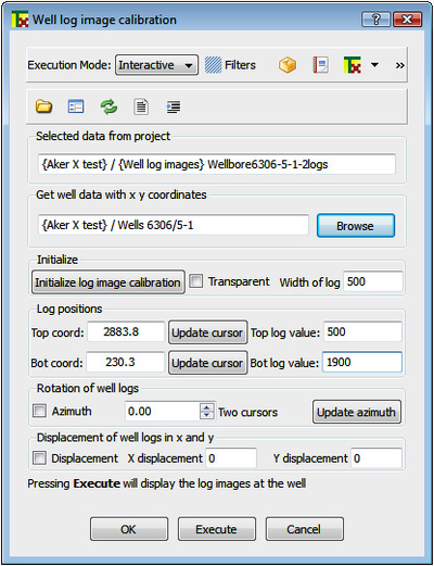
The actual command object is called Well log image calibration and is found under Images->Additional display. Activate the command object on the preferred well log image.
Calibration is done by referencing two points on the image with its real depth values. Click first Initialize log image calibration. This will put the screen in 2D mode and display the image.
Find a top reference point on the well log image and mark it by the cursor using right mouse click (or keyboard p). Apply Update cursor to get the cursor value into the Top coordinate field. Write in the corresponding value in the Top log value box.
Repeat the same procedure for a bottom point in the well log image. The calibration is now performed.
Menu for well log images
Displaying well log images
After calibration, browse in the well that correspond to the well log image. Press Execute to display the well log image attached to the well. Adjust the width and angle and displacement of the well log display to get optimized.
Save the command object with all the parameters. You may rename it to tell exactly which well it is used for. Another well must have a copy of the command object and its own parameters.
Different well images cropped from the same master well image can use the same calibration. Select your image part using Geocap or an external image program. Activate the command object and adjust the width parameter and display.
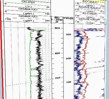
Two well logs cropped from an image and displayed in a 3D scene
Transparent well log images
The well log images are opaque and may shadow a seismic section. An option is to extract the lines in the image. This is done by the Transparent option.
The white part of the image is removed and the remaining information is converted to a polydata set and displayed in black. The log set is also saved in workspace under the name loglines. An example is displayed in the picture to the right.
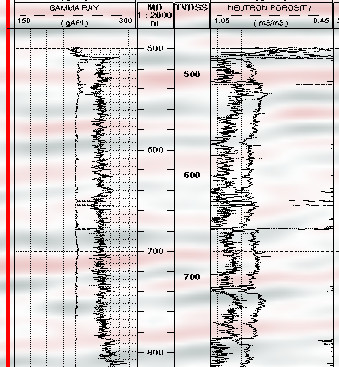
Well logs extracted from an image and displayed
Example of calibrating well logs from pdf reports
This example uses a log report from NPD's facta pages .
The PDF report was taken into Ghostview and the proper well log image was clipped out and saved. Then the calibration was done according to the documentation.
The well log image was then displayed with some low opacity so that the 2D seismic in the background could be seen.
The well bore is in red to the left and the whole display is correctly placed in the 3D scene. One has to realize, however, that the logs are from the well position and not where they are stretched out. It is therefore a personal taste if one wants to display the overall log sheet or clip out single logs.
Be also aware of that Geocap can read different log formats (i.e.LAS) and display them as curves out from the well string. The well data with logs must then be placed in the Wells folder.
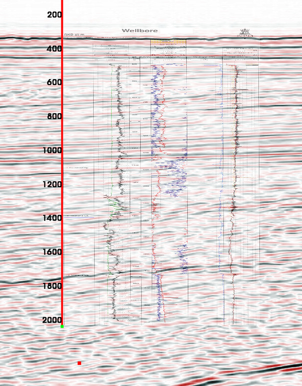
Well logs calibrated and displayed together with seismic