Introduction
You can use the SEG-Y Analyzer dialog to analyze SEG-Y files. Using the dialog you can scan the file and then save the file configuration parameters as a JSON file. Later when reading the SEG-Y file using one of the SEG-Y reader tools you can provide this configuration file to ensure correct reading.
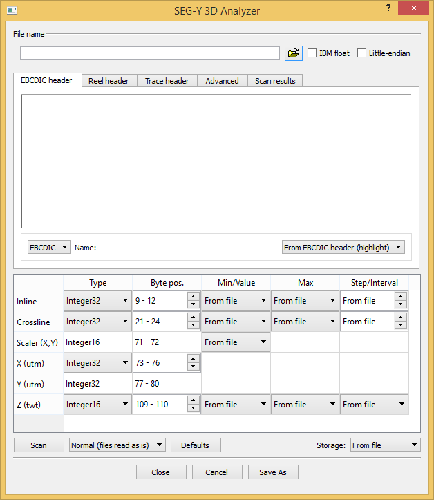
The above figure shows the dialog for 3D files. The 2D version is similar. The main difference is that you will have to set byte positions for both inline and crossline in the 3D import, while in 2D there is of course only one shot point column. The 2D import also has a Analyze panel that lets you fix anomalies in the SEG-Y file.
For more information about the SEG-Y format, see the SEG page SEG-Y standard: http://www.seg.org/resources/publications/misc/technical-standards
Analyzing a SEG-Y file
To analyze a SEG-Y file:
- In the Seismic Explorer toolbar click the button SEG-Y. In the pulldown menu click Analyze SEG-Y 2D File or Analyze SEG-Y 3D File. The dialog will open.
- Click the browse buttton at the top of the dialog to select the SEG-Y file to analyze.
- Using the controls in the dialog to adjust to the properties of the SEG-Y file. See the section The SEG-Y analysis dialog for a detailed explanation on how to use this dialog.
- Once the settings are correct click Save As to save the parameters in a JSON file.
The SEG-Y analysis dialog
This section describes the elements of the SEG-Y Analysis dialog.
IBM float
The SEG-Y standard revision 1 defines SEG-Y files stored with IBM floating-points to have the data sample format code in the binary file header set to 1. Since SEG-Y files may have this as 1 regardless of floating-point format, check the IBM float checkbox to specify IBM floating-point.
Little-endian
Most modern computer architectures use big-endian byte order. You may come across SEG-Y files, especially older ones, that have been stored with little-endian byte order. When that happens, the information under tabs Reel header and Trace header looks garbled. Check the Little-endian checkbox to fix this problem.
EBCDIC Header
The SEG-Y EBCDIC header (textual file header) contains 3200 bytes of readable characters. SEG-Y revision 1 allows the header to be encoded in ASCII. Use the encoding combobox to switch between EBCDIC and ASCII encoding. The resulting data set's name is either based on the file name or byte positions in the EBCDIC header. To set EBCDIC header byte positions simply highlight the section you want as data set name. The label between the comboboxes always shows current name.
Studying the text in the EBCDIC header tab may give you useful information about byte positions, etc.
Reel header
The SEG-Y reel header (binary file header) contains 400 bytes of binary values that affect the whole SEG-Y file. The information in the Reel header tab includes sampling interval, number of samples per trace, data sample format code, etc.
Trace header
The SEG-Y trace header contains 240 bytes of binary trace attributes. The Trace header tab allows you to browse through all trace headers in the file. The four 'player' buttons takes you to the first-, previous-, next-, and last trace. You may also enter the trace number directly in the trace number line edit. If you change a setting (e.g. Type) that affects the information in the Trace header tab, you need to enforce an update - click button for next trace, for example - for the information to change.
The Trace header tab is an invaluable tool for deciding unknown byte positions. If e.g. shot point byte position in your SEG-Y file is unknown to you, try stepping forward trace by trace by using the Next button and look for a number that increases by one for every other trace.
Scan results
After performing a Scan the results are displayed under this tab. If more than one file is selected, the scan results are updated continuously as the different files are scanned.
Settings table
The settings table contains widgets for setting relevant trace attributes to accommodate all the different flavors of the SEG-Y standard:
- Shot point or Inline, Crossline: Type, Byte pos., Min, Max, and Step can be adjusted
- Scaler (X,Y): Value and Byte pos. can be adjusted; Type is fixed to Integer16
- X: Type and Byte pos. can be adjusted
- Y: Type is fixed to the same as X and Byte pos. is fixed to the corresponding bytes immediately succeeding X
- Z: Type, Byte pos., Min, Max, and Interval can be adjusted
Import 2D seismic
Make sure you have read about the different elements of the import menu above, before you read this section.
Import of 2D seismic can be done in 4 steps:
- Browse for the seismic file.
- Analyze the file, looking for anomalies.
- Scan the file to make sure the import settings are correct.
- Execute the import.
Step 2 and 3 are explained in detail below.
Analyze file
The analyze process scans the SEG-Y file looking for anomalies:
- Unassigned shot points (Taper)
- Unassigned navigation (Taper)
- Missing traces
The Analyze dialog always report the first and last trace. If only two lines appear in the dialog with nothing reported in the Anomaly column, the analysis is done.
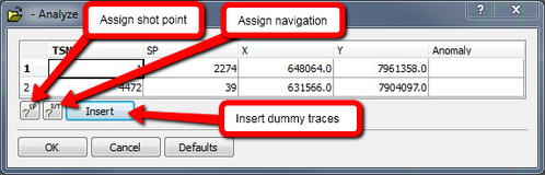
SEG-Y analysis panel
A common anomaly found by the analyze process is taper. The phrase Taper On denotes traces in the SEG-Y file that occur before full fold is obtained. If the phrase Taper Off is reported it means that taper occurs at the end of the file. Taper are usually handled by assigning shot points to the corresponding traces. The assigning algorithm suggests a shot point for the taper trace next to the normal trace. Go with this suggestion unless you have special considerations. Shot points are then assigned to the taper traces in an orderly fashion. You may also assign navigation to the taper traces; inspect the X- and Y columns to see whether they already have navigation, and if it is correct. Navigation is assigned by way of extrapolation.
The analysis may find missing traces. Those are traces that normally should have been in the file but have been omitted for some reason. The Insert button will insert dummies for these missing traces.
Analyze uses the natural ordering of shot points into tuples (singles, pairs, triplets, quadruplets) to detect anomalies. If the SEG-Y file contains variations, for example both pairs and triplets, the analysis will fail. The exception to this rule are traces at the beginning and/or end of the file.
Scan file
It is always recommended to scan the SEG-Y file before import, to make sure the settings for each trace attribute are correct. Click the Scan button and observed the results in the Scan Results tab.
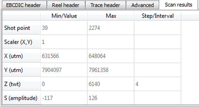
Example of scan results
Shot point byte position
If the Min and Max values for Shot point looks odd, the byte position could be wrong. The default shot point byte position in the SEG-Y 2D import is 17-20 in the trace header, but in some cases this is not always correct. If the byte position is wrong try the following:
- Look for information about the shot point byte position in the EBCIDIC header.
Select the Trace header tab to view the SEG-Y file's headers trace by trace. The byte positions' values are continuously reported as you move through the file. By closely observing how the values change you should be able to determine the correct byte position.
Shot points often appear in pairs, i.e. they change every other trace.
Use the Shot point, Byte pos. spinbox to set the appropriate byte position.

Coordinates and scaler
In some cases the scaler may be wrong, causing the X and Y values to have to few or to many digits. This can be adjusted by changing the scaler multiplication factor.
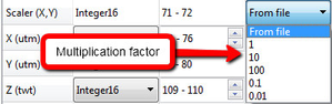
The SEG-Y format states that a negative Scaler denotes division, e.g. Scaler = -10 means divide X and Y with 10. Geocap, on the other hand, uses pure multiplication, e.g. Scaler = 0.1 means multiply X and Y with 0.1.
The scaler may be 0 on file. This will lead to X and Y being 0 in the dataset. Fixing the Scaler to 1 is usually the correct setting in this case.
Z(twt)-range and sample interval
The Z values are usually correct but you can have a look in the EBCIDIC header to see if there is any information about the sample interval or Z-range.
Import multiple files
Geocap lets you import multiple SEG-Y files in one go. Since Analyze and Scan makes no sense for multiple files, they are disabled. A combobox with analysis options is enabled instead. The entries are:
- Normal (files read as is)
- Full auto - Equivalent to both Auto assign shot point and Auto assign navigation.
- Auto assign shot point - Equivalent to pushing assign shot point button in Analyze dialog for all files.
- Auto assign navigation -Equivalent to pushing assign navigation button in Analyze dialog for all files.
- Auto omit taper on/off - Equivalent to manually omitting taper traces by setting Shot point Min all files.
Insertion of missing traces cannot be performed during import of multiple SEG-Y files.
Before importing multiple SEG-Y files, try importing a single file making sure that your settings are correct. Make a note of your settings.
Import 3D seismic
Make sure you have read about the different elements of the import menu above, before you read this section.
Import of 3D seismic can be done in 3 steps:
- Browse for the seismic file.
- Scan parts of the file to make sure the import settings are correct.
- Execute the import.
Step 2 is explained in detail below.
Scan file
Loading 3D seismic can be a time consuming job, and it is very important that the import settings are correct before starting (to avoid having to do the job again). Therefore, 3D import is usually performed by first setting the import settings, and then performing a scan on the very first inlines only. This is achieved by leaving the Min/Value Inline setting at From file, but setting the Max setting to 10 lines higher than the first inline. This means you have to know the start value of the Inline. You should be able to find this in the Trace header or the EBCIDIC header.
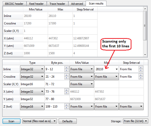
Inline and Crossline byte position
If the Min and Max values for Inline or Crossline looks odd, the byte position could be wrong. The default byte positions in the SEG-Y 3D import is 9-12 for Inline and 21-24 for Crossline in the trace header, but in some cases this is not always correct. If the byte position is wrong try the following:
- Look for information about the Inline/Crossline byte position in the EBCIDIC header.
- Select the Trace header tab to view the SEG-Y file's headers trace by trace. The byte positions' values are continuously reported as you move through the file. By closely observing how the values change you should be able to determine the correct byte position.
Use the Inline/Crossline, Byte pos. spinbox to set the appropriate byte position.
Coordinates, interval and scaler
The coordinate Interval often gives us a good indication of if the coordinate is set correctly, as most seismic cubes have an interval of 12.5, 25, 50 meters or similar. In some cases the scaler may be wrong, causing the X and Y values to have to few or to many digits. This can be adjusted by changing the scaler multiplication factor.
The SEG-Y format states that a negative Scaler denotes division, e.g. Scaler = -10 means divide X and Y with 10. Geocap, on the other hand, uses pure multiplication, e.g. Scaler = 0.1 means multiply X and Y with 0.1.
The scaler may be 0 on file. This will lead to X and Y being 0 in the dataset. Fixing the Scaler to 1 is usually the correct setting in this case.
Z(twt)-range and sample interval
The Z values are usually correct but you can have a look in the EBCIDIC header to see if there is any information about the sample interval or Z-range.