Depth conversion and sediment profiles
- Erlend Kvinnesland
- Former user (Deleted)
Introduction
Geocap can compute sediment thickness data sets, based on seismic interpretations of the sediment base and the seafloor, and velocity information. The result of these computations can later be used for the sediment thickness calculations needed in UNCLOS Article 76.
The seabed and the base of the sediments can be interpreted from Seismic data as two horizons. The sediment thickness can be calculated as the vertical distance between these two interpretations. In order to do UNCLOS Article 76 sediment thickness calculations, we need to know the sediment thickness in meters. Normally a seismic line is interpreted with Two Way Travel (TWT) as the z coordinate. Two way travel time is the time it took for the sound signal to travel from the Seismic sound source, down to the reflector and back to hydrophone. This time is normally measured in milliseconds. We need to convert from TWT in milliseconds to depths in meters. This operation is called a "depth conversion".
In order to do a depth conversion, we need to know the velocity of the sound signal in the sediments. In the dept conversion process we can use a data type called a velocity profile. A velocity profile is a data set which consist of interval velocity information combined with the seismic interpretation for each horizon of a seismic line. The interval velocity stored in the velocity profile is the average velocity between two reflectors.
The first step in generating a sediment profile based on seismic interpretations is to generate a velocity profile from the interpretations and velocity information. Read about: Importing Velocities.
In this section:
Velocity profile
A velocity profile contains interpretations of horizons of one seismic 2D line together with interval velocities in the intervals above each horizon. In order to create a sediment thickness profile, at least two horizons must be interpreted; the seafloor and the sediment base. The profile may also contain interpretations of other horizons between the sediment base and the seafloor.
A velocity profile contains all the information needed in order to depth convert the horizons and compute sediment thicknesses. In a velocity profile, the horizon interpretations are in TWT, and each point in the interpretation has stored the interval velocity of the interval above this interpretation. For example, if the velocity profile is based on an interpretation of the seabed and the sediment base, each point on the seabed will contain it's depth in TWT, and the water velocity, while each point in the sediment base will contain the depth of the sediment base in TWT, and the interval velocity in the sediments.
The computations needed in order to create a sediment thickness from a velocity profile are quite basic, and can be derived from the fact that depth equals time multiplied by velocity. The vital step in depth conversion is determining the correct interval velocities, which is done when generating the velocity profile.
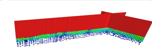
Two velocity profiles. The colors represent the velocity. The points are Dix interval velocities, computed from stacking velocities.
Generating a velocity profile in Geocap is done by executing the command Generate Velocity Profile. The command resides on the Velocity Profiles schema, and must be executed on folders with this schema. This command has two main methods for creating velocity profiles.
- Using a velocity lookup table
- Using stacking velocity information.
Each method is described in the following sections.
Velocity lookup table
One way of creating a velocity profile is to base the interval velocities on a lookup table. The interval velocity is the average velocity in an interval. The table lets the user specify which interval velocity to use in the interval above each interpreted horizon. This interval velocity will be used in the entire interval from the specified horizon, to the interpreted horizon above. This velocity can either be specified by a constant value, or using a velocity function.
If a velocity function is used, it is evaluated for each shot point on the horizon. The function should return the interval velocity of the entire interval between the specified horizon and the horizon above. In the example below. The function returns the interval velocity between the seabed and the sediment base.
The function may contain one or more of the following variables:
- T_BOTTOM
- which is the TWT of the horizon at the current shot point.
- T_TOP
- which is the TWT of the horizon above at the current shot point.
- DT
- equals T_TOP - T_BOTTOM, or the interval thickness in TWT.
- V_TOP
- is the interval velocity of the interval above the current interval.
The intervals are computed starting at the top interval. For the top horizon, T_TOP, and V_TOP refer to the time at sea level and the velocity above sea. Both of these values are defined to be zero.
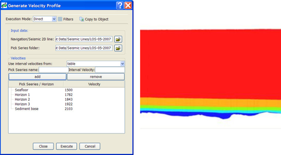
A velocity profile generated using a velocity table with constant velocities. The profile is generated from five interpreted horizons.
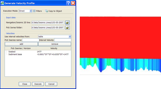
A velocity profile generated using a constant water velocity and a function for sediment velocity. Notice how the velocities increase where the sediments are thick, which is according to the formula used.
Stacking velocities / RMS velocities
Geocap can use velocity information based on stacking velocities, in order to compute interval velocity for each interpreted horizon and create a velocity profile.
A stacking velocity analysis is done on some shot points, often with a regular interval along the seismic line. The results of an analysis at a shot point are several velocity picks, where each velocity pick consists of a depth in TWT and the stacking velocity at this depth for the shot point.
In deep water, the stacking velocity will cohere with the RMS velocity. Based on RMS velocities, the interval velocities on the same picks may be computed using Dix formula. This is explained in #dix. The result after running Dix formula on an RMS velocity dataset in Geocap, or a Stacking velocity dataset as a substitute, is a dataset where each velocity pick now contains the Dix interval velocity for the interval between the pick, and the pick above.
Geocap can create a velocity profile based on the interpreted horizons and the corresponding Dix interval velocity dataset. This is done using the Generate Velocity Profile command.
Based on Dix interval velocities, the interval velocity in the interval between the interpreted horizons may be computed at the shot points with a velocity analysis. This is explained in the in following section. After this, the velocities for the rest of the points on the interpreted horizons not containing a velocity analysis are computed. This is done by interpolation and extrapolation. For points on the horizon between two velocity analyses, velocities are interpolated using a linear interpolation between these analyses. Some points on the interpreted horizons are only related to one velocity analysis. This is the case at the beginning and the ends of the seismic line. In these cases, the velocities from the nearest velocity analysis are used directly.
The user may set some properties to the velocity profile generation:
Constant water velocity
The command has an option for using a constant water velocity. In this case, the computed interval velocity for the first interval is replaced with a constant value. This will not have any effect on the following intervals. In other words the velocity computations in the sediments will be unaffected by this option.
Velocity pick in sediment base
The command has an option for ignoring velocity picks below the interpreted sediment base. The idea behind this option is that if a velocity analysis has been done using a pick below the sediment base, the velocity may be overestimated, and should in some cases case be considered ignored.
If these velocities are ignored, one may choose between two alternatives. The first alternative is to use the last known velocity inside the sediments instead. The other alternative is to compute the trend from the last two velocities inside the sediments, and extrapolate a new velocity. In both these cases one may add or remove a percentage of the resulting velocity.
Interpretations below the deepest velocity analysis
If interpretations of a horizon (i.e. The sediment base) is done deeper than the deepest velocity analysis at a shot point, the last known velocity in the velocity analysis will also be used below the velocity analysis.
The Shelf module contains a method for depth conversion of interpreted lines, by using stacking velocities. The method will be described in this chapter
Dix formula
If you have a velocity data set, you can use Dix formula for converting RMS velocities to interval velocities. Dix formula has been implemented as a command, so you can simply right click a data set with the schema Velocity, and select the Dix formula command. The dataset should be on the form described in Importing Velocities. A copy of the data set will be created, and placed in a folder called interval velocities. As an approximation, stacking velocities can be used as RMS velocities.
Sediment cross sections
When you have created a velocity profile, you can depth convert it, and generate a sediment profile. This is done by right clicking a velocity profile, and selecting the command Calculate Sediment Thickness. A sediment profile will be generated, and placed in the folder 3. Sediment data/Sediment profiles.
This sediment thickness data can be used for sediment thickness calculations using the command described in Sediment Thickness Calculations .