Composed grids
- Former user (Deleted)
- Erlend Kvinnesland
- Harald Sund (Unlicensed)
Introduction
Composed grids is a concept of grids of unequal resolution that are located in the same folder in the Geocap project. The need for this concept arises from cases where a small part of the seabed is mapped with a fine resolution and the adjacent public domain data is mapped with a coarser resolution. Mapping and particular cross sections on the continental shelf can then be extended across grids of different resolution apparently seamless.
The Composed grids feature was originally developed for UNCLOS users which frequently have grids of different resolutions. The technique is however general and may be used for all mapping projects facing similar situations. See also Combining grids using ramps.
On this page:
Case study
The text and pictures below go through a case where a fine resolution grid is combined with a coarse public domain grid to see the overall map and cross section for the combined area.
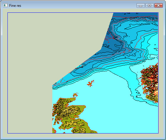
A detailed grid of fine resolution
The fine grid shall be combined with the coarse grid.
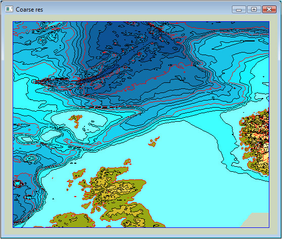
An overall public domain grid of coarse resolution
The grids are organized in a project folder with the schema type Composed Grids.
The grid with the finest resolution shall be first in the folder. The sorting is alphanumeric and can be safely achieved by placing 01_ .. 02_ .. in front of the grid name.
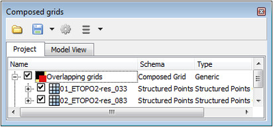
Folder with composed grids
The same part of the fine grid that overlaps the coarse grid has to be removed from the coarse grid so that no overlap is present. This is a trim operation and the result grids after trimming away the overlap are placed in a new folder with extension ..._trimmed.
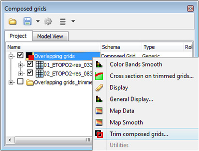
Activating the CO Trim composed grids
Composed grids with overlap are trimmed using the menu in Trim composed grids.
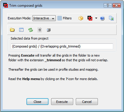
Menu for trimming grids that have an overlap
The trimmed grids are also of schema type Composed Grids. The trimming is just necessary if grids overlap. If they don't overlap (if the trimming has been done elsewhere), they can be utilized directly.
Presently there is a blank overlap zone because the grids are still in a pure grid format. That overlap zone will be revealed when mapping, while in making cross sections the overlap gap is neglected.
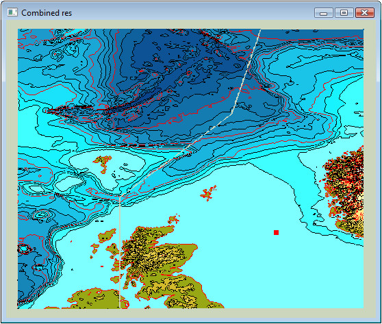
Mapping of trimmed grids having no overlap
Zooming in on the mapped overlap area one clearly sees the different resolution and the overlap zone.
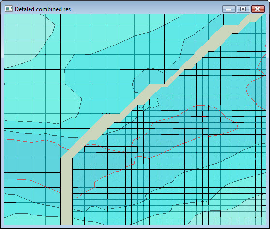
Detail of composed grids showing unequal resolution
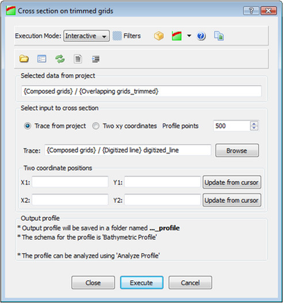
Cross section menu for composed grids
In order to make a cross section profile, activate the command object Cross section for trimmed grids.
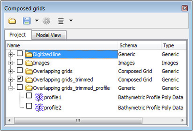
Folder with cross section profiles
The profile is written directly to the folder for Bathymetric Profiles under 2. Seabed. If that folder doesn't exists the result of the cross section generation is a new folder with the profile.
A 3D view of combined grids and the cross section profile. There is no gap in the profile.
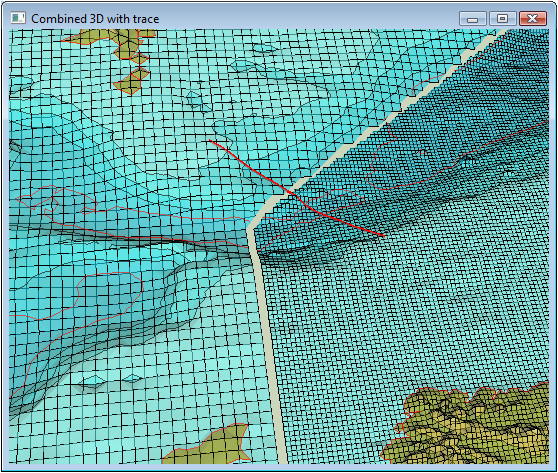
Combined grids and cross section trace
The profile has the schema type Bathymetric Profile so it can be immediately be subjected to the Analyze Profile command.
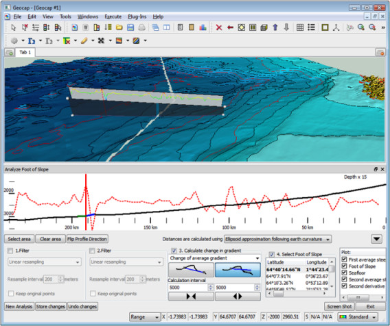
Bathymetric profile analysis panel