Vertical Image Calibration
- Erlend Kvinnesland
- Tore Sannes (Unlicensed)
- Harald Sund (Unlicensed)
Introduction
This tutorial will guide you through creating a vertical calibrated image (VCI) from an old scanned seismic image. The process can however be performed on any image. All you need are two datasets:
- Image
- Navigation
We assume you have already imported the image and navigation (or digitized a navigation line).
Open VCI menu
The VCI menu is opened from View > Vertical Image Calibration (XCal in older Geocap versions). The menu should appear in the same panel as your project, like the screen shot below:
This menu consists of 3 steps (tabs) that you need to complete in order to complete the vertical calibration.
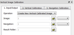
Input/Output
- Click the Image browse button and select the folder where your image resides.
- Select the image you want to vertically calibrate in the drop down box.
- Click the Navigation browse button and select the folder where your navigation/digitized line resides.
- Select the navigation/digitized line you want to vertically calibrate against in the drop down box.
- Click the Result folder browse button and select the folder where you want your vertically calibrated image to be stored.
Vertical Calibration
The vertical calibration uses a cut off range and 3 calibration points. The cut off range usually starts at 0 and stops at the max depth/time of your seismic image. Everything above or below this cut off range will be eliminated from the VCI. The 3 calibration points specify the orientation and scale in vertical direction.
- Click the 2. Vertical Calibration tab to start the vertical calibration.
- Set the Stop value in the Vertical Cut Off Range to the max time/depth in your image.
- Set the first calibration point to 0, click the Pick button and click on the corresponding value to the left in your image.
- Set the second calibration point to the stop value in your cut off range, click the Pick button and click on the corresponding value in the middle of your image.
- Set the third calibration point to 0, click the Pick button and click on the corresponding value to the right in your image.
- Use the Focus buttons to zoom closer to each point and re-pick them for a more accurate selection.
You should now see two white horizontal lines across your image. One at 0 depth and one at max depth.
If you want to keep parts of the image above 0 or below the max depth of the seismic image you can do it by adjusting the cut off range after you have set the calibration points. In the example above we could set the cut off start to -100. This would preserve the well-information at the top of the image.
Navigation Calibration
- Click the 3. Navigation Calibration tab to start the navigation calibration
Locate the first shot point in your image and find the corresponding shot point in the Tie Points list in the menu.
Select the Tie Point in the list, then click the Pick button and click on the shot point in the image.
Locate the last shot point in your image and find the corresponding shot point in the Tie Points list in the menu.
Select the Tie Point in the list, then click the Pick button and click on the shot point in the image. You should now see a line of points along the shot point line.
Continue this process with the points between the start and end points if needed.
Note that everything to the left and right of the dotted line and everything above and below the white lines will be cut off on the completed VCI.
- Click the Save button in order to create the VCI
Display
- Locate your VCI in your result folder.
- Right-click the VCI dataset and select Display
It is possible to do seismic interpretation on the vertical calibrated image. Just open the Tools > Seismic Interpretation panel and pick the Vertical Calibrated Image instead of Seismic.
It is possible to convert a VCI to a seismic by "Convert to Seismic". Then the result may be exported as a SEG-Y.