Outer Limit Line Generation
- Erlend Kvinnesland
- Former user (Deleted)
- Harald Sund (Unlicensed)
Introduction
The Outer Limit Generation command lets you create a preliminary outer limit by combining the formula lines, and the constraint lines. This outer limit is only preliminary because it is possible to maximize the outer limit by connecting all bays with a shortcut line that is less than or equal to 60 mile which will mean a lot to the final outer limit line. Read more: Maximizing the Outer Limit Line.
In this section:
The Generate Outer Limit Menu
The Generate Outer Limit menu is opened by right-clicking the 4. Outer Limit folder and selecting the Generate Outer Limit command.
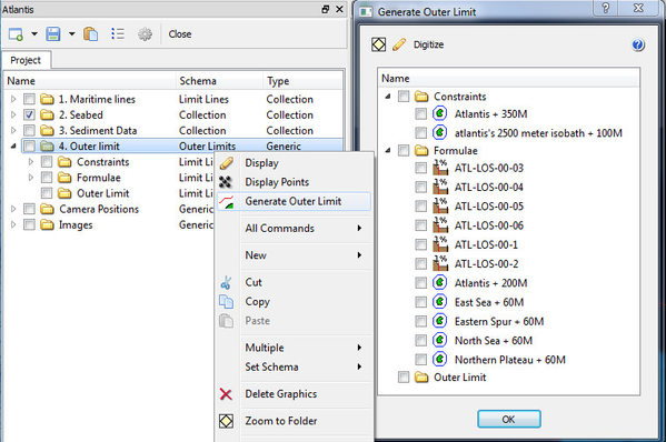
Opening the Generate Outer Limit menu
The tool bar buttons in this menu works on the checked datasets in the folder view. Using the buttons you may Display and Scale to datasets, and Digitize a new line based on the checked datasets.
Digitizing the outer limit line
The standard procedure when digitizing the outer limit line is the following:
- Tick the check box next to all lines relevant for the operation and display them from the menu.
- Click the Digitize button.
- Start with a crossing point between two lines, i.e at the 200 M line.
- Continue with selecting line pieces.
- End up at the 200 M line and click End Digitize.
- Select a name for the outer limit line and click OK. The line will be saved to the 4. Outer limit/ Outer limit folder.
To ensure that the outer limit is digitized in the best way there are several ways to select line pieces during the digitizing process:
- Clicking with your left mouse button in the display window will snap the digitizer to the closest line.
- a - absolute point. Will digitize a point at the exact cursor position.
- c - crossing lines. Will digitize near the crossing point between two lines. Geodetic correct by default.
- l - line point. Will connect to the closest line. Will interpolate a new point.
- m - multiple selection. Will automatically digitize all points from previous point to picked point.
- s - select line piece. Will automatically select the line piece until it reaches a crossing line. Geodetic correct by default.
- f - flag insert. Will start a new line piece.
- d - delete. Will delete last point.
Note that the distance between points on the outer limit line should not exceed 60 nautical miles. Thus, for each point you digitize you will see a circle around the selected point. This circle indicates how far 60M is from the selected point.
A more detailed description of the digitizing process can be found in the article: Digitizing the Outer Limit Line
A note on input lines
Digitizing is dependent of proper preparation of input lines. The requirements are simple but important:
- All lines that are supposed to be one line piece must be just that. This is also called one cell in the technical term. Read more about how to view cells and sort them into one in: Geocap Data Types
- Closed lines must be properly closed in order for the digitizer to operate across the common start and end points. Type in the shell command poi end to see the end points of a dataset and then zoom in and visually check the closure.
Correct geodetical calculation of crossing points
It is assumed that all formulae and constraint lines so far are generated in such a way that the points making up the lines are geodetically correct. All crossing calculations will then be performed geodetically correct.
A standard distance between initial generated boundary points could be 1000 meter or 2000 meter. When two geodetic lines are crossing it is therefore necessary to secure that also the crossing point is geodetically correct calculated. The default is to perform a geodetic correct calculation. This is done by re-sampling each line piece that is subjected to crossing to a much denser line set of geodetically correct points. The small line pieces are then used in the crossing operation. Default line piece when crossing is 100 units which are meters if all lines are in meters.
There are a few shell commands to handle the described feature and geodetic calculation of line crossing.
geo set geocro on | off
Sets geodetic calculation of crossing lines on or off.
To see the effect of geodetic calculation an option could be to perform two calculations with and without geodetic correctness and compare the result.
geo set lenres length_resolution
Sets length of resolution of the crossing lines to _length_resolution.