Depth conversion of 2D seismic sections
- Former user (Deleted)
- Erlend Kvinnesland
Introduction
Depth conversion of time data into depth data can also be performed for 2D seismic lines. It utilizes in principle the same basic techniques as described in Depth Conversion of time surfaces. In addition extra attention is paid to transforming the wavelets into a new wavelets form using spline based algorithms.
On this page:
Formula for depth conversion
Depth conversion applies the formula
Standard formula for depth conversion:
- Seismic_lines_in_depth = Seismic_lines_in_time x Velocity
The seismic lines are depth converted according to the corresponding velocity field. The velocity field describing the input velocity can be:
Velocity options:
- Time-velocity cube
- Stacking velocity data along the same line
- Lookup curve for y (time) to x(depth)
- Constant velocity in meter per second
Command menus for seismic depth conversion
Seismic lines (or seismic sections as they are also called) is organized under a folder having the schema Seismic Data. The seismic lines themselves have schema Seismic Line.
The following command menus for depth conversion of seismic lines are present:
Command menus for depth conversion of *Seismic Lines*
- seismic lines in a folder->Depth conversion of seismic in a folder. Allows for depth conversion of all seismic lines in a folder.
- seismic line->Seismic depth conversion. Will convert a single seismic line.
The menu contents are basically the same in the two cases and should be easy understandable. A few comments are described below.
Specify to which depth value depth conversion is to be performed.
Enter values for new vertical resolution if needed. Normally one could have a finer resolution for the depth converted seismic grid. The really fine resolution should only be used for powerful machines or low memory data types. Try to keep the new grid size below 30-40Mb if possible in the normal case.
Velocity data
To achieve a satisfactory depth conversion apply a smooth velocity field or a smooth velocity cube. It is assumed that the velocity data is covering the seismic outline. If not, the depth conversion will use the nearest velocity data that is covered by the outline.
The generation of a time-velocity cube and trimming towards check shot wells is described in Cube gridding from stacking velocities.
Output
A new outline is generated after depth conversion for each seismic line. The new outline makes a rectangular frame from top to the specified depth. The seismic lines are depth converted following these principles:
- Seismic lines that have an outline within the velocity field are depth converted and saved back into the project.
- The default option is to create a new folder bearing the same name with the extension _depth.
- If saved back into the same data the converted depth seismic will override the time seismic. In that case, make sure that you work on copies of the original seismic lines in time. It is thus necessary to take a copy of the complete folder with seismic sections and run this command object on the folder doing a depth conversion on all seismic sections in the folder.
- Seismic sections that are not depth converted if they are outside the cube or velocity field are listed in the message area.
Gallery
A time-velocity cube was gridded from stacking velocities. A seismic lines was depth converted.
The seismic line before and after depth conversion is arranged in a connected viewport presentation showing the same coordinate area of the result.
One sees that the depth data is greater in value than the time data.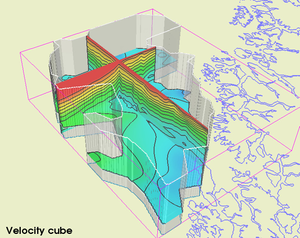
Time-velocity cube located outside the coast
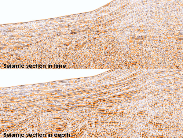
Details of a seismic line converted from time to depth